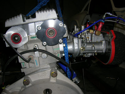
Been distracted.
Anyway did start knocking up something inside.

Saturday, June 28, 2008
Bit quiet
Posted by
David Powell
at
11:36 PM
0
comments
![]()
![]()
Sunday, June 15, 2008
Tunnel Part Duex
So Part 1 is basically complete ready for welding. Couple of tweaks needed but goes in and out just about perfectly. Its totally solid and rigid.


Posted by
David Powell
at
2:24 AM
0
comments
![]()
![]()
Saturday, June 14, 2008
Tunneling
First piece.


At this time its just screwed together. Completing it will be a staged operation.
I will add a top plate next, it must be removed for that. I hope it stays in shape when removed. Should do as its only held in with 3 small screws...
Then I will get the inside seams TIG welded. To hold its shape.
Then remove the radio frame, bare metal it and the outside seams can be welded and the radio frame can be welded to the alloy.
Next job then will be adding a new face to the front, to extend the radio frame backwards a few inches and give a matting surface for the smaller rear section that will be removable.
I have accounted for a few things, firstly that the heater vents can be operated, also that the heater unit can be removed without removing the tunnel and obviously that the engine and box will be fit and is removable.
I will add a filling plate for the gearbox also.
Oh and also the radio slot seems the perfect place for a glove box, so I will make a boxed section and add that to the tunnel and make a lid. Be nice to have somewhere to put keys and whatever.
I can line the inside of the tunnel with some heat/sound proofing.

Posted by
David Powell
at
10:07 PM
0
comments
![]()
![]()
Wednesday, June 11, 2008
Few more things completed.
Boot wiring is complete, all other wiring is complete. Starter wire added.
Rear fuel lines added and checked for leaks. My fuel sender from the Rover gives me a gallon reserve.
 Been over the whole engine and checked all bolts.
Camshaft pulley bolts are uprated ones as the stock ones are barely up to the job and often fail. These are much stronger and loctited.

So basically this leaves the gearbox tunnel and exhaust, painting the floors. Fit main fuel line, redo rear brake line.
Plus building the car/engine bay up, which is easy as it all fits! Cause I made it all! I need to get a new windscreen and the wilwood brakes. Bar that stuff have everything done.
I shall try to get my head around this gearbox tunnel front section over the next two evenings. Then the engine can go back in, the rear gearbox section can be fitted/made later.
Not sure what to jet the carbs with.
36mm chokes, which with a half decent flowing head should give me the required power. Afterall massive chokes are usually only needed on shit heads, like a Triumph head. I'd hope to squeeze maximum potential from the chokes @ 7000rpm.
This is a temp measure anyways...I guess if the conversion works to my liking I will wedge some fuel injection on it.
I shall use long-nose idle jets...I'll get some in 53-55-57 that should allow me to test 7850.1, 7850.3 and 7850.2 idle holders...Shall start on 57 with 7850.1.
Main jet probably 150.
Emulsion Tube 6
Aircorrector 170
Pretty standard main jet stack.
Pump jets 38.
200 needle valves fitted, fuel pressure already set @ 3.5psi using 8.5gram floats.
The LC1 should make light work of the tuning anyway. Plenty of Emerald maps to sort the ignition curve.
Posted by
David Powell
at
10:37 PM
0
comments
![]()
![]()
Monday, June 09, 2008
Forthward
A productive afternoon/evening


Engine can go back in once I sort the front section of gearbox tunnel, hopefully get that done this week. Few small other jobs, need to add the alloy fuel line and plumb that in. There is then no reason I cannot I add fluids and have a pop at starting it, maybe at the weekend... I got a 1.5metre piece of 2" exhaust pipe I can ram up the manifold outlet, just need to blag a silencer. Once the engine is back in it'll take only a few hours to attach all the stuff to it.
Posted by
David Powell
at
11:28 PM
0
comments
![]()
![]()
Thursday, June 05, 2008
Cam Timing
Another job done.
New water pump in and new belt tensioner. Piper wide cam belt.
 Made a little bracket to attach the dial gauge firmly to the head as magnetic bases do not stick to alloy.
Timing is done via lift at TDC. Exhaust according to DVA wants 0.023" of lift @ TDC. Which it has. Exhaust cam may need some minor tuning to get a sweet idle.


Basically just have to stick some gaskets in the carbs and needle valves, set the fuel levels and it could be fired up with the exhaust manifold fitted an a section 2" pipe attached.
Will leave the cam cover off till I shows signs that it will run, allows me to keep lubing up the new cams between any periods of cranking it over. Then its 20mins @ 2200rpm.
Nervous 20mins, oil system needs to be checked for leaks, water system for leaks and pressure, the cam followers have to fill, the cooling system needs to work :) A lump cast iron it is not, things have to go well!
Posted by
David Powell
at
9:47 PM
0
comments
![]()
![]()


