Almost done. Thats as much room as possible I think.
 Will get the pedal box and part of the bulkhead made and then some welding can commence, plenty queued up and lots of progress possible then.
 Pedals are all good. I'll kink the foot of the clutch pedal back into line and make some adjustments later.
 To retain the normal pedal pivot rubber covers I can graft on the pressed up area from the removed bulkhead to replicate the area as normal.
Once this is ready and welded the engine mounts will be done too, I can then remove the motor and build a bulkhead and get on with ignition triggering, finish the plumbing and wiring.
Leaving exhaust, prop, gearbox tunnel and plenty of small jobs.
Wednesday, January 31, 2007
More pedal fun
Saturday, January 27, 2007
Pedal mods
Started on remaking the pedal boxes.
Two flanges cut off, boxes butted together. The boxes will then be "boxed" up to the middle outer bolt holes...So to stiffen the whole thing. There will a range of other adaptions.
 Will be seam welded together at the top. The pedals will need final bending adjustment once trial fitting has taken place.
You can see I have bent the clutch pedal, the brake pedal was already bent from previous fiddling.
 I will make a new master cylinder bracket, 1 piece and add alot of strengthening, also some "tangs"or extensions on the bottom at the back, these tangs will have a nut welded on them I can then bolt the master cylinder bracket to the added box section on the lower pedal box, with bolts from through from the footwell, access impossible from above. These tangs will stop any bending or deflection in the backsurface of the bracket.
In the image above the right hand area where the master cylinder bracket and the pedal box meet and are bolted together will be removed, as there is not room for a horizontal area sticking out 15mm...This inner side of the pedal box and bracket will bolt to the new vertical section of bulkhead via 5 capitive nuts, 3 on box, 2 on bracket.
This new bulkhead section will have a brace that matches the current bulkhead brace which sits between each master cylinder, just now it will be sit on the inner side and run down about 105mm to make a new bulkhead area.
Pretty simple. This gives me 48mm between the trumpet and the new vertical area of bulkhead for filter which is just enough for what i have in mind...Minus 10mm for clearance and engine vibration allowance and 15mm for filter depth thats 23mm between the foam and the trumpet, you can basically run ITG filters on the trumpet ends as they are nearly totally free flowing. So thats fine.
 Poached this off Bowler does Revs, Shiftlight, Speedo, Mileage, Trip, 0-60 timer, totally adjustable acceleration timer and it cooks your dinner too. So that solves MOT speedo thing and gives a totally accurate digital speedo..Sorted.
Tuesday, January 23, 2007
Check out my Trumpets :)
Check these suckers out :) Never seen ones as big as this before!
 Getting an air filter on will be fun. Atleast now if I make the bulkhead suitable for these + slim ITG panel filter I can run just about any trumpet / filter or throttle body combo in the future....
The cones and base flanges are not made together, they are two piece, so can possibly press the cones out of the flanges...Make a custom alloy ITG backplate to fit the filter, this plate would slide over the cones and be welded to them, about 1inch from the open end. Due to the increasing radius and such it would be a very neat and easy job.
I can then refit the flanges and get some weld tacks on them.
Then can get a shallow foam ITG filter which just covers the open ends of the trumpets with 1 inch air space behind the openings/ends. You can run these panel filters really close to the trumpet openings. You need only 20mm or so..The filter element is 15mm think...So I need another 40ish mm beyond the end of the trumpets is needed on the bulkhead mod.
Still pondering the clutch pedal options... :)
Extra work but worth it I think in the longer term.
 Need to shave a few mm from the two centre trumpets as they will clash, so close is the manifold spacing.
 BRROOM!
Sunday, January 21, 2007
Making problems for yourself.
Found these going pretty cheap on ebay. They are for 45 carbs I am led to believe, 90mm long and WELL big. They are just like ones often seen on the most potent Ks running throttle bodies. I really want to get them to fit :) This leads to some serious issues with the clutch pedal system. I am currently pondering my options, there is no rush to resolve anything yet.
I could possibly find just enough room if I remove the spacing between the master cylinder's , basically moving the clutch master cylinder over and then bending/extending the clutch pedal over to its normal location... butting the pedal systems right up together.
This would mean removing the bolting faces from the insides of each pedal housing and even more material, welding the pedal housings together to make a 1 piece unit. This unit will have the mastercylinders as close as possible on the bulkhead...I can weld the brackets together also.
I can also make both pedals work on the same pin with a small nylon spacer between them so meaning I can get them very close together.
I can remove the bulkhead brace panel from between the master cylinders and add it back on the clutch side, this panel can then form the top end plate for the bulkhead recess.
I can I think if I am cunning find another 3/4". Each pedal boxes bolt to the bulkhead by two bolts on the lower bulkhead section (vertical) and 6 bolts on the actual flat surface the master cylinder brackets bolt to.
The pedal boxes obviously have a protruding flange each side with 3 holes and captive nuts to bolt to the lot to bulkhead...By hacking the outer flange on the carb clutch side away, I can make my bulkhead 3/4" further outward towards the master cylinder...
I can weld some captive nuts to the vertical plane of the outer end of the pedal box, replacing the ones on the cut off flat section, the aim is to bolt the inner side of the pedal box to the vertical section, section I will build below the rehoused brace plate....So saving the thickness of the original mounting area...
I will need measure this lot up :)
Friday, January 19, 2007
Water works
Found some alloy tube with swaged ends to start finishing the plumbing.
No huge progress.
Few details below. Need to borrow a K-Series head from the engineering shop to make the water rail for the other side. Aim to get a wad of stuff ready for welding and get this bloke I know round to Tig it. Then its onto the ignition triggering.
Few details below. Need to borrow a K-Series head from the engineering shop to make the water rail for the other side. Aim to get a wad of stuff ready for welding and get this bloke I know round to Tig it. Then its onto the ignition triggering.
 That's basically the deal on oneside. Pump just dangles its pretty solid.
 This little bracket will be welded to the tube this obviously holds the water rail in location.
 Radiator fan sensor in background this always goes on the inlet side of the water system, I like this best, as it on the outlet it gives a false reading. On the inlet side it measures when the radiator is needing assistance.
  The black thing is stock thermostat housing I think I will modify this eventually but for now it will do for eyeing it up and testing. The open outlet is the standard bypass circuit inlet this will need blocking. I would like to knock out this whole housing and weld an alloy tube to the block but that can be done before the engine goes in finally, need the engine out for that. Its only weakness is at the redline, which is a funny rubber seal joint I don't like the look of.
 Hardly an assault on it :)
Thursday, January 11, 2007
Further progress
Made some small extensions ready to be welded to the suspension turrets, for the engine mounts rubbers to sit . Made the steel pins for the end of the mounts. Once my mount rubbers arrive I can get the lot cleaned up and welded.
I got a 5 .75" inch trigger wheel ready to fit on the pulley. It will need opening out to 95mm I/D.
Should have some alloy pipe sections arriving shortly. These will make a 1 piece water rail in alloy. This goes over the exhaust manifold from the back of the head. The swirl pot will have a mount plate welded on and it'll mount on the cam over. The water pipe on the drivers side will bolt to the engine mount.
I'd hope by the end of the month to have a fully mounted engine with ignition system, water system, electric system. Leaving bulkhead, exhaust, cams, propshaft...There are numerous other small jobs.
Lot of loose ends to tie up. I can't remove the engine again to play with the clutch or mod the rear gearbox extension, make the rear mount till the engine mounts are made, as the engine is perched in place, exactly as I want it!
I also need to check the existing timing marks for TDC and make new ones if needed? I needed a 16mm plug spanner which I didn't have to remove the spark plug.
Its coming on.
Sunday, January 07, 2007
Arranging things
Another afternoon messing around with it. Some good fortune with the ignition leads I was using before they seem to fit fine on the K plugs and such like. They are from a Ford CVH engined Escort injection 1990>on.
The coil pack sits neatly on the bulkhead and its lucky it all fits cause I can't fit the coil pack anywhere else close by withut longer leads. It looks very tidy anyway.
Best of all no rewiring needed!
 I had hoped to get the engine back on the bulkhead more about an inch further back but this is the best location as to get it 1 inch further back needs serious mods to the handbrake area and mini crossmember under the prop.
 Trial fitted some carbs, adjusted the levers and Magard linkage so it suits the spacing change, actually a bitch of a job as usual, cause the adjustment screw on the centre levers always hits the rod-end rod. Also had to take a small nick from the manifold as the levers were beaching on it at the back. Manifold spacing is very close, you can't run K&N backplates as they clash. I think my best option is to buy a thin'ish Pipercross 1 piece element and make my bulkhead to suit, I can make my own backplate for the Pipercross unit, I have a real knackered one here to rob the captive nuts off.
 Shows where the carbs end up. Manifold needs some porting and also brass takeoffs adding for the MJL.
 Overview from the front.
I want this install to have the same flavour as my 1300...Totally minimal and very neat.
Coming on. I am getting back into it. Its new year! Be summer soon!
I must admit after the amount of mods, repairs, fiddling I did last year I was hoping for the winter to just consist of swapping my head back to triumph valves, doing some lightening and nothing too hardcore. Its taken a while to get motivated to fiddle with it...
Saturday, January 06, 2007
Mounting but not humping the engine.
Did a bit today.
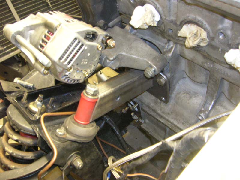
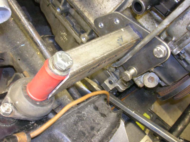
Made some bridges for my mounts. The polybush is just a dummy, its exactly the same O/D as the steel tube I will replace it with once I get down the engineering shop.....This is pretty much exactly what Caterham use.
The tube I will make for the ends where the polybush can be seen will have a just over 1/2inch hole through them for the 1/2" bolt. I will find and weld on two big flat washers on the bottom where the tubes sit on the engine mount, to spread load a bit eh?
I need to use the lathe to finish off the mounts.
The E-Type engine mounts need a small box section making up and welding on to extend the plane the mount is sat on, backwards, will also house a captive nut/bolt for the mount... this is so there is something flat for the entire thing to mount on!
I could have made a 100 different styles of mount this just ended up as is cause its made use of what I had!
Its a bit over-engineered maybe :)
Have to heatshield the alternator its gonna get smoked by the exhaust Not sure it'll end up sitting so low...Could rehouse it on the otherside if needed...
So to move on I need to buy some new mounts as they are not 100% in shape having had a 300kilo e-type engine on them! also make the flat sections they sit on, once thats done I can get them both in place and welded.
Then onto the rear gearbox mount, I'd like this to be removable rather than welded in...So will probably cut 2 recentangles of steel about 8mm thick, 4inches long by 12mm wide, cut two threads into each, at the ends ..weld them to the top of the chassis rails and run a "u" style mount that slips down between the rails and bolts in at the top...
Also cut off the straight outlet pipe from the water outlet manifold that goes on the back of the head...refaced the remaining flange ready to accept some alloy pipe sections I will make up. These will run from this outlet over the exhaust manifold, forwards to meet some flexible hose by the timing belt cover. This manifold and pipe will be one section and mount to the engine. You can buy a similar item from caterham as with the engine in RWD form the outlets are all wrong. Space is a bit lacking so custom item needed.
Once the engine is mounted at the front I can undo the 210NM front pulley nut and get the pulley on the lathe...I couldnt touch it with the engine loose on the floor! Too light even with me standing on it.
Did I mention a bare K is under 90kilos :)
Friday, January 05, 2007
Doesn't making titles get tiring?
Isn't working with steel fun, not!
Took me most of the afternoon to make two plates for the engine.
Hardwork! Arms like popeye.

 Need to make the bridges to the suspension turret next.
Steels a bit heavy but its reliable!
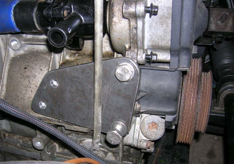
 Also had another look at the alternator, it will go on using the other boss/mount point on its body. It actually lines up perfectly with the bottom pulley, leaving 2-3mm between the belt and the cambelt cover. As the pulley has 5 small grooves for a flat belt I will need to machine it for a single groove belt.
The groove will go as far forward on the pulley as possible and cannot go too deep into the pulley as I need to have material left to bolt on the trigger wheel for the ignition system.
This other mount on the alternator isn't as strong as the proper one but I think it'll be ok. I can make a stronger 3 dimensional top mount/adjustment system that is rigid, probably some alloy thing, that should make the loads on the alternator even out. You'll see.
 Best pickup the pace a bit soon!
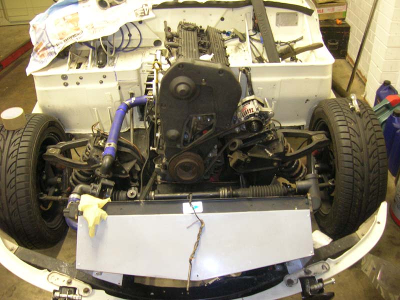 I think it'll look a nice neat install. Exhaust is going to keep passengers feet nice and warm :)
Ordered a tube of "adheseal", that might assist in starting on the fixed part of the gearbox tunnel. Yes it'll be mainly bonded in, made from alloy. Good stuff for panelwork this adheseal sticks with such grab and its flexible, only downside it takes 24hrs to go off. I will make the rear part of the tunnel removable as per normal, but maybe 50% will be attached to the body.
Subscribe to:
Posts (Atom)