Still doing nothing on the K-Front...bar looking at various products...
I'd imagine once I start the ball rolling things will happen extremely quickly! It'll be done in no time. Cash is my main constraint...I have spent too much time and dollar chasing performance and fun this year as it is..I am saving some pennies atm and intend to waste not 1p on the car, yet.
Once the engine and the gearbox are mounted. I shall just need to remake the bulkhead/paint, make a gearbox tunnel, shorten the prop...Thats the physical installation done. So I am not too worried atm...I guess there is a weeks work there.
Timing the camshafts is a bit of a pig as you need 3 dial gauges and some bolt down plates...DVApower does this for about £30 he's an hour away, so I will probably just stick the engine in the Alfa and take it there. Saves making and buying any gauges...Once you have timed the cams once you can add marks on them and refitting them to another engine or the same one is just a matter of finding TDC and aligning the marks on the pulleys.
Then its just a matter of adding a trigger wheel and a mount/sensor for the Megajolt ignition, wanging some carbs on it, plumbing it up waterwise...I can use my existing wiring loom/fuel system, ignition without a single mod!
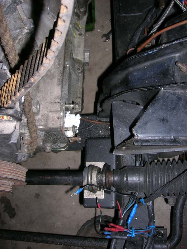
First two purchases will be the centrally actuated hydraulic release bearing system seen below and a decent new style starter motor from a caterham. This plate bolts on in place of the steel nose on the Type9 gearbox, it houses a seal.
 You press a release bearing onto this hydraulic slave. You can pack the slave out with an alloy spacer if its too far from the clutch...
A neat solution, saves very tight clearance by the chassis rail with an external slave, or running a cable system...
I sold my excess parts on ebay : VVC mechs for £62, VVC actuator for £22, VVC airbox and manifold/injectors for £72 and the VVC cams for £24....and the MGF dash for £10 £190!
The engine/bellhousing were £450...
The engine now only owes me £260!!
I spent £20 on an exhaust manifold, so far the project owes me £280 for which I have virtually fitted engine and gearbox.
-----------------------------------------------------------
Oh and I sent off an entry for the 10CR (10 Countries Run) today. Will do the event with Spitbang, Steve.A.
Niether of us have working cars atm :) But I entered "The Beast Mk2" on the premise it will be in one piece then, if not we can do it in Steve's car.
I REALLY enjoyed the drive to the Ring and back in the spit, real comfy ride :) ... so should be fun! We can also do some Ring laps if the place is open! hooray!
Wednesday, November 29, 2006
K-series musings, 10CR entered...
Wednesday, November 15, 2006
Decisions
Well never wanting to rush into anything, been pondering my engine mounting and way ahead...
I suppose some action will take place soon, I doubt it will take long to get this motor mounted.
Just sorting a welder out. Josh gave me one ages ago, yet to see if it works, just need to pickup a few bits and bobs and more importantly teach myself to weld!
Not sure at 105amps it'll be beefy enough for some jobs I'd like to do, so might try and pickup a decent 170amp one...Also these cheapo welders are a bit crap where I'd like something I can make pukka consistant welds with and on thick materail...
Need to pickup some steel too. I want to minimise my costs on this engine swap so part of that involves some patience!
Tuesday, November 07, 2006
Engine mounting decisions
Been doing some pondering about the neatest and best way to mount this motor.
I was thinking about from the side of the block...But the mounts would need to be at a very steep angle to meet the chassis rails, also the mounts would be quite low on the engine...
My initial thought about this is the footprint of the mounts would be quite thin in relation to the engine, also low, so it might be inclined to move excessively as the mounts would be so low on the block and not spread out wide?
I can only use the mount holes in the block, so I'm stuck with what I have to work with...The passenger side mount holes are very low...Also it would look a bit Heath Robinson?
As such I have pondered another method which utilise the stock front engine mount, stock engine mounts and locations...
This beings a couple of small issues, the alternator will need to run on the bigger pulley, the alternator will need to be switched for the Lotus/MGF item for it line up here. This may be good news cause to get a trigger wheel on the pulley for megajolt I cannot use the smaller of the two pulleys (the power steering one)...So that will leave the front most of the two pulleys redundent and I can add a trigger wheel over this to fire the Megajolt...The plate I am pondering as seen below would also allow me to mount the crank sensor on it, also the water pump and gives a wide footprint...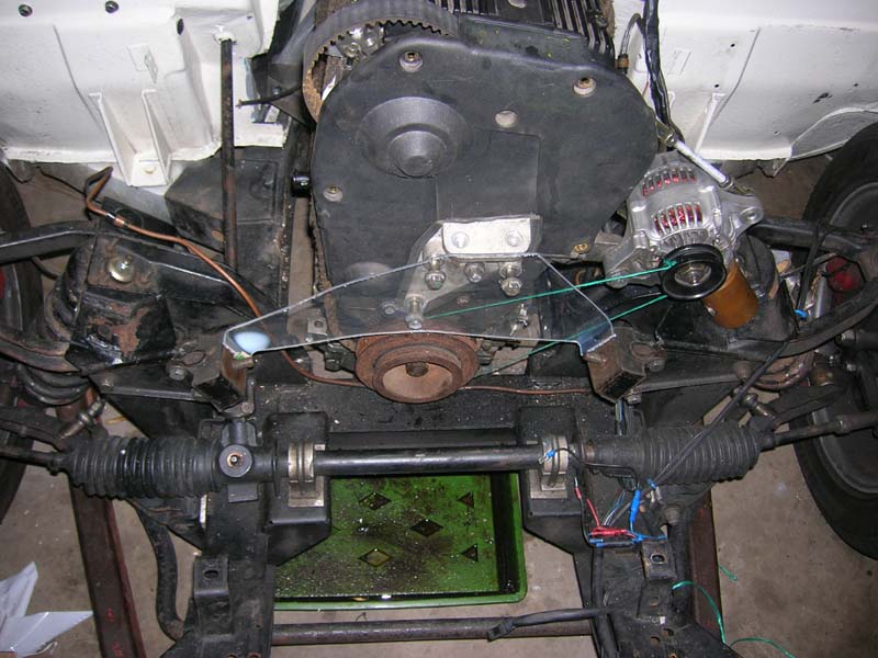 Perspex dummy shows my idea. It would be bolted to the engine mount via 4 high tensile bolts..Needs spacing out from the mount 1/2" by using some cut down steel bar pieces with holes drilled through welded onto the back of the plate, to space it out, the high tensile bolts pass through the plate, spacers into the alloy mount then into the block. Should be ok.
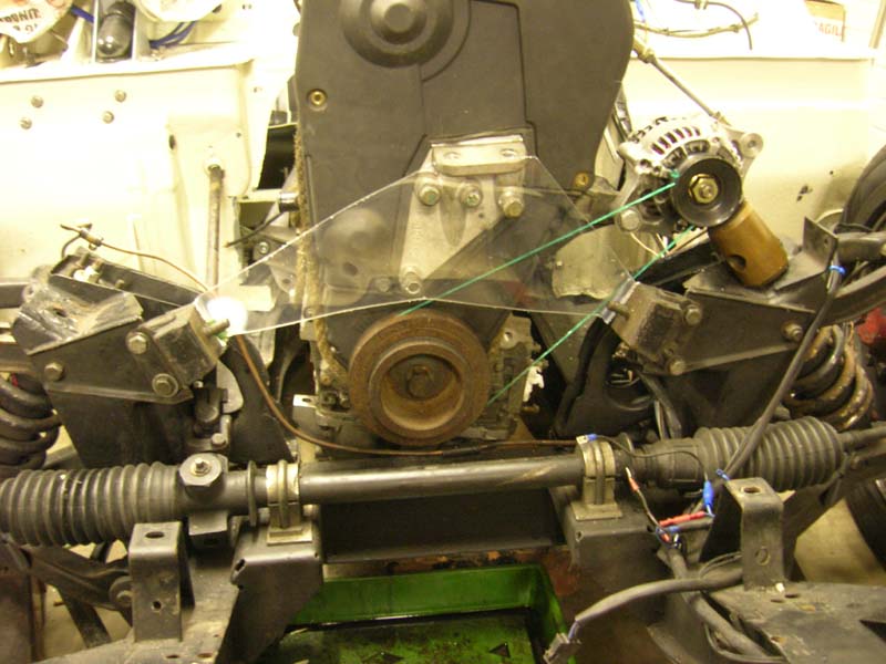
This is the neatest and easiest of my ideas, 1 piece and saves buying anything bar steel.
The plate would be one piece with the ends bent 90deg to attach the engine mounts, then I would weld horizontal sections to the top and bottom of the plate which run along its entire length to add strength against forward and rearward twisting...Basically check out the drivers side mount of the standard spitfire engine plate...It would replicate this exactly but the top and bottom horizontal brace sections would span the entire plate in one piece...
I think its best idea....I could make it from alloy too...I need to assess my crank trigger system and few other details before commiting to the idea.
This also leaves a nice space for the exhaust, oil filter, etc etc there is nowt at the side of the engine.
Saturday, November 04, 2006
K-Series engine is in place.
K-Series does indeed fit nicely. Minimal chopping of chassis needed. All cuts shown below. Was definately the way forward to wedge it back a few inches. Bonnet clearance good too about 1.5inches (due to my special bonnet!)
Few changes of initial planning regarding getting it running.
I want to be out to play in April really at Mallory trackday (with stock rear suspension?!) So, for the time being I will stick some 45 Dellortos on it, and weld a trigger wheel to the front pulley and use my megajolt system, mainly cause its all in place, just plug it in and there isn't a weeks work making a wiring loom etc also less cost.
I can switch to throttle bodies and such like in the future. I should be able to blag 2d advance map from Emerald basically just need the max figure used on a K. I spy a manifold for 45's on ebay atm...This should mean once the engine mounts are made it'll be straightforward.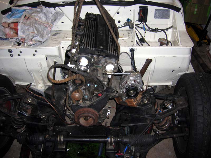 Its in! Thats the angle they sit at.
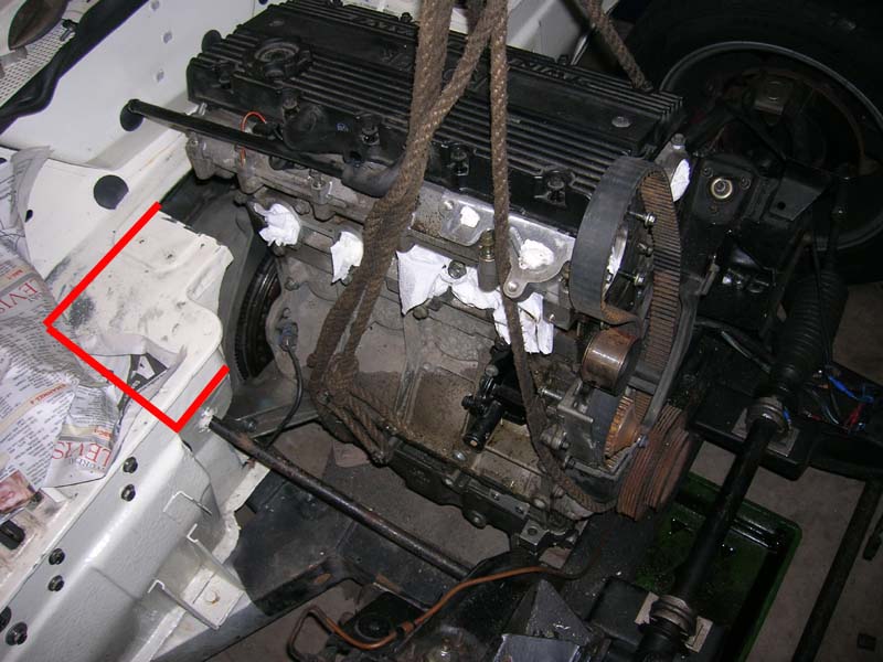 Shall lower the bulkhead in this area to give me room for carbs/throttle bodies.
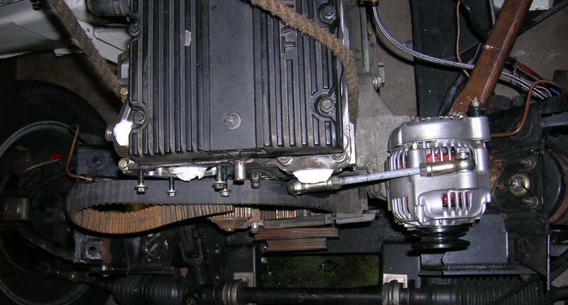 Alternator lines up on standard bracket and fits..Just needs a grooved pulley...Or more likely I will remove the crank pulley and machine a groove in it, for a standard belt...At the same time adding a trigger wheel to it...The K-Series flywheel ignition trigger system isn't good for megajolt cause its has 4 teeth missing its a 36-4 system not a 36-1 as per the ford kit....?
 The gearstick location isn't that bad! Atleast for a midget like me! Maybe ok for leaving it there! Handbrake needs twisting towards the passenger side...
 Plenty of options for engine mounts...I will probably make my own...Just have to remember a hole for the dipstick, thats covered by an alloy plate as seen at the base of the block.
 To save removing too much material from the chassis rails I ground the box case a bit, both sides as there is a 1cm pointless protrusion here.
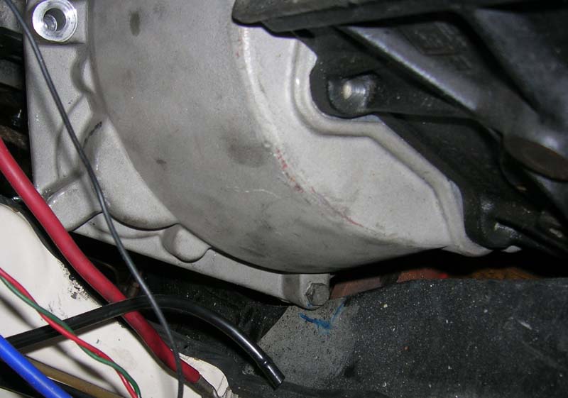 Chassis needs a nick removed here I can fettle a few mm from the bellhousing too, no problem...Atm the engine and box aren't quite level as its beached on this area, all the final areas needed adjustment as marked now...There's a good 7/8" lip on the chassis rail here which is more than enough once its ground down level with the main rail.
 Chassis required the area where the old spitfire gearbox mount plate goes to be ground out, just as deep as a the bolt holes inorder for the box to clear and also enable easy removal of the box and engine as 1 item...You gotta plan these things!
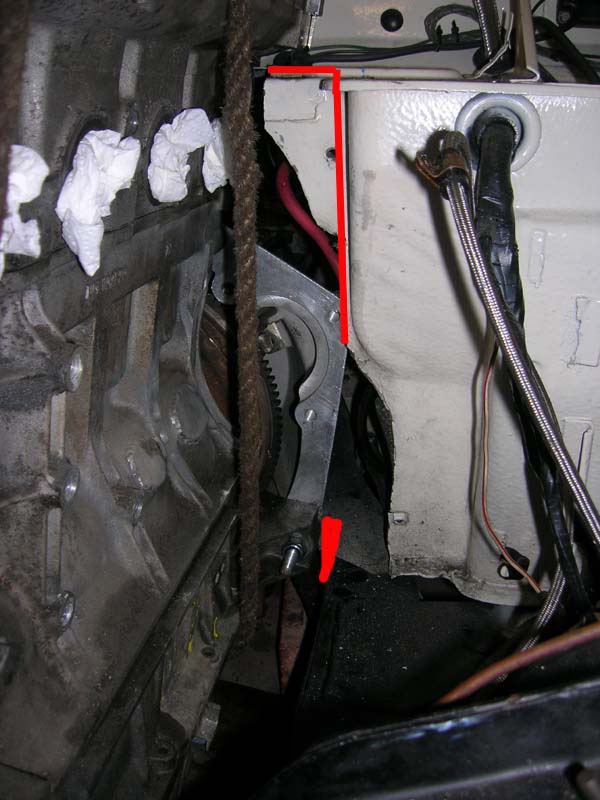 Bulkhead will cut at the redline, this leaves the rearward plane left on the upright part by the wiring hole, leaving something to tack on a new panel too...I have already planned my bellhousing/gearbox cover system...
 Plenty of room as my bonnet top is flat over this area. The crankshaft centreline will be about 2cm lower at the front that will the spitty engine, it will be laid totally flat when fitted. Bit lower C of G.
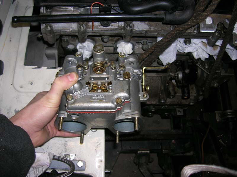 Carb will end up about here probably more towards the engine as this a conservative estimate of its location...Enough room for 25mm trumpets and an ITG panel filter.
 Red area will be fettled too this is for the hydraulic clutch mech. Handbrake needs moving left.
Basically ya can't moan at that can you? I had the thing fitted in and basically its final location in less that 2hrs....ready for a rear box mount to be made and a set of front mounts...
Almost made to be! I didn't want any rail adjustment, rack moving and stupidity...Its a good idea to get the blueprints for engines before trying to fit them! I had the blueprints of the block for Zetec, K-series and Duratec and the K-Series. I worked out the others wouldn't fit with the box between the front and centre main crossmembers without sump changes and cross member adjustment, or locate in a rearward position, K-series goes in with 18mm to spare between the cross members with no real mods needed.
I am quite a happy bunny..I was feeling nervous as I hacked out sections of my car, but my diagrams where right and it all worked out good!
Next step is to pull the motor out again, make final adjustments to the rails then it will stay out and a rear box mount is be made, once thats made back in and ill rig up some front mounts...Then its onto bulkhead.
Ready for Chop Chop
So I just aimed the engine at the hole...Looks ok no obvious problems so far. I think chassis modification will be very minimal if any at all. The key to the so far hopefully simple installation (atleast) is the moving the entire engine back behind the chassis rail. This will make for more complex bulkhead reconstruction and gearbox tunnel, mainly due to the throttle bodies, I hope to use direct-to-head type that are not very long and make up the tract length with trumpets...I hope that the clutch pedal can stay in its current location with a shallow foam air filter, but thats along way off me thinks and I'll need to save some pennies!!
 One K-Series dumped in rough location. It will sit inclined in the engine bay angled over the passenger side..Thats how ya do it ya see. Its currently perched on the chassis rail but after some chopping of bodywork it will drop behind the chassis rail and sit ALONG way back from the standard engine location, all things considered.
I have spent a couple of hours freezing my arse off (till 1am)measuring, checking and getting a mental picture of any potential problems before I get out the power tools and make a firm commitment to K-Series power.
I don't see any big issues so tomorrow it will be chop day and i'll lower it back and down and stick the bellhousing on it and make any chassis rail nips.

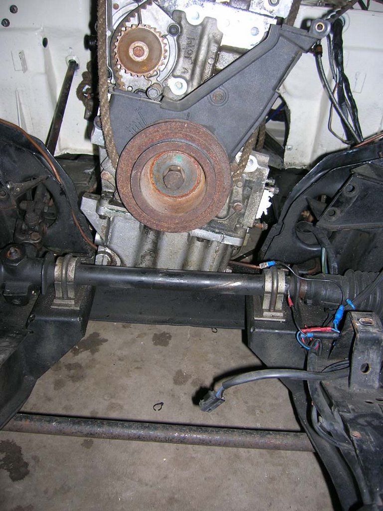
A QED Caterham bellhousing, the engine is only bolted to the bellhousing by 4 bolts, big suckers two below the centreline and two at the top...You can see the plate thats been added to take a Mini Hydraulic slave cylinder. I will retain this system I think...This will JUST miss the chassis I think of the plate will need to be shortened which is no bother the slave bolts on right at the front.
 To get the engine where I want an initial cut will need to made here to get this mount through the bulkhead, as marked in blue. This is due to the bellhousing mount. This will stick out above the chassis, the bellhousing and lip on the chassis rail will or will not need a minor fettle to allow the bellhousing to sit down in the rail...I may be able to get the engine in and out with this piece still in place once the final bulkhead is made, so it will cut along two lines only and fold it back for now...I'll have repaint the entire bulkhead anwyays.
 Again shows this mount at the rear...The rear of the engine will only be a few cm's lower than it current sits...I see no big problem having measured up carefully...As said I may or may not have to make a small adjustment to something as the engine is currently shown 4inches further forward than it will sit. Any small issues will be mainly as it will then be just into the area where the rails come together closer. I forsee the lip of the chassis rail needing trimming and possibly a small recess made in the bellhousing, but it may clear...From the eyelet the rope is going through the bellhousing angles quite sharply towards the block over 8cm, then makes another angle towards the block...The chassis rail will be around the area of the 2nd angle...I'll post of pics once the engine is moved back and the bell fitted.
 This will be my next cut, at this stage its just about doing as little cutting as possible to purely get the engine and box to sit in their final location. The rear of the engine will be 15mm from the heater box.
 Plenty of room for it, its less wide than the base of the spitfire block...Once the cuts mentioned have been made I will be able to drop the engine backwards and behind the rack, chassis rail (4inches) , it will fall 7cm at the front to be perfectly flat in the car and also to the crankshaft centreline matches the spitfire position, but it will loose the inclination the spitfire engine has.
You would have a great deal of hassle to fit where it is atm (the stock engine location) You'd need to get a small pulley (which I may do anyway!) or move the rack and chassis rail, mod the sump etc etc...
The oil filter/adaptor will need to be adjusted/binned...It may actually still fit but it'll reduce my potential exhaust area...I'd really like a nice 4-2-1 manifold eventually so will need to plan ahead! I will make an alloy plate thing enabling use a remote filter, oil cooler setup with an inline thermostat...Not sure of the plumbing atm but I sure I can rig something up for the time being a simple alloy plate with two take offs on would do! Frontline have this same issue on the MG conversion and they want £96 for an adaptor, screw that! not even oil cooler compatible.
 Imagine this engine back 4 inches there's plenty of room for the pipes of a manifold, this was a concern on paper...Also rear bellhousing mount wont need any adjustment to bellhousing or chassis bar a couple 2mm shaved from the lip of the chassis rail...
You can see the engine block mod to fit a starter on this side..Thats another area of concern...Caterham sell a lovely one but its £134...
I got a big ugly ford one free, so will attempt to use that, but again the exhaust will need some consideration even if for the time being I use a standard manifold...It will be a tight fit probably end with a bespoke job with a bunch of snakes heading towards the wheelarch and back.
 Again once 4inches back the filter would probably fit on, need to consider the primary length I want on any future exhaust, whether or not I want room for 4x 1.5" primary's to go down the side of the block and chassis rail or two 2nd'ary pipes...
Thats it for this evening.
Friday, November 03, 2006
K-series exhausts
I see a few variations in exhaust manifold type. The MGF VVC angles upwards towards the front of the car, not ideal, also its footprint where it meets the downpipe is bigger so it takes up more room. Did a quick bit of ebaying and found a cheapish Rover 200 1.8VVC BRM model manifold that angles back towards the bulkhead a bit...So it looks like it'll just miss the engine mounts that came with the motor...Either way it'll be alot better than the MGF model...I was told they are all the same, but they are not!
All these claggy manifolds are internally welded...So me thinks ring welding the outside then porting the inner pipes to match the gasket is the way forward.
I read that the exhaust system on the FWD cars like rovers is MILES better than the standard elise and MGF, cause the secondary (2-1 bit) can be MUCH longer in the FWD cars and this will be the same in mine, the MGF and Elise has basically a few inches of secondary pipe work where as the FWD cars have a couple of feet...The power gains from a special 4-2-1 are good on an elise or MGF but less improvement on a FWD which came with longer 2nd'ary pipes as standard...
I'll post some pics of things soon, but at this stage there is not alot to show!
Me reckons this manifold will fit...£30 with delivery...Not that cheap but by the time you go a load of breakers, petrol, time, etc its a good buy.
Hopefully it'll miss the starter motor...! Thats the next problem, setting starter motors on fire...? Have to make a heat shield.
Thursday, November 02, 2006
Fiddling with engines
The K-series is now ready to mate with the box and aim at the hole sometime soon.
I removed the pulley's, VVC mech, cams all that lark tonite. All good bar one dodgy lobe on an the exhaust cam, bit of pickup marking and lost about 0.5mm off the tip, few marks on the cam follower too...I'll need to replace the followers with new ones anyway as they aren't good enough to planish off and also both cams will be replaced with 285H versions.
I think the standard VVC exhaust manifold from just about any 1.8 VVC engine (MGF, Elise, BRM Rover) maybe useable and it'll just fit round the engine mount and allow a cheaper solution to the exhaust issue..It will miss the bulkhead and aims at exactly the space I have left for a pair of secondary tubes between engine and chassis rail...The manifold is a bit crap as the primaries are short but it will still give 180+HP and can be ported out. I can always get a real pukka one made at a later date if I like the conversion.
Also the frontline chaps who do the Midget conversion sell an exhaust manifold...that way fit as the midget 1500 system is basically the same as the spitfire? Will check out that option too.
I will not spend a penny on anything atm. If the engine fits where I want it / once its mounted I will firstly get it all plumbed up leaving my main expenses as : Throttle bodies, trumpets, filters, ECU, Cams, vernier pulleys, blanking kit for VVC mech and getting a 2-1 exhaust piece made up to join the manifold to the rear section, which will be 2.5inch or 2.25inch bore.
I am sure the wiring will be fun!
Few more items to remove from the engine bay, take the seats out and I will need to chop the bulkhead...and get the engine in the hole on bricks...
The water system is a bit pants the thermostat is on the inlet to the engine from the rad...? With a 2nd pipe recirculating water from the oulet to the inlet to open the thermostat...Thats about emissions and minimising warm up time...
I will ditch all that lark..The engine will have the EWP on the drivers side on the side of the block pushing water in right by the pump, no thermostat will be fitted, or actually it will but with the thermostat mech removed..The stock pump impeller will be removed/ground off and EWP will run the cooling. I can't remove the pump completely as its needed for the cam belt.
Haven't done much more...Bloody cold! Wind changes and suddenly we are worrying about global warming!
I got the chills and sliced my finger open undoing a 8mm bolt when a spanner snapped. Kept on working and there is blood everywhere!
Not sure how long this conversion will take, but it won't be that quick, but then you never know.