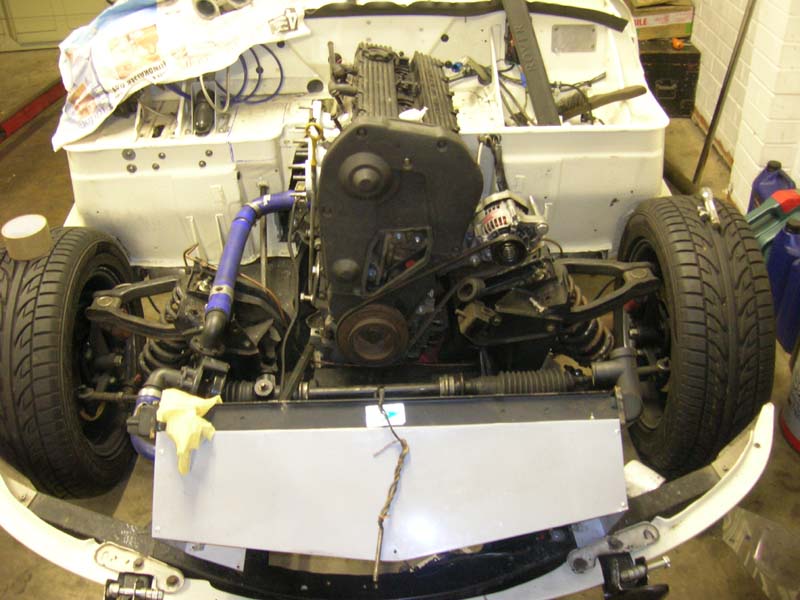
Did a bit today.
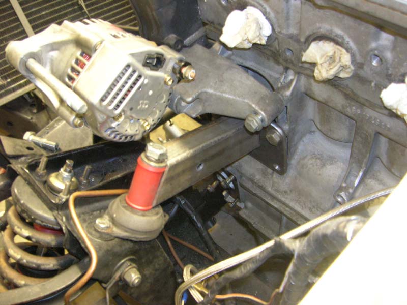
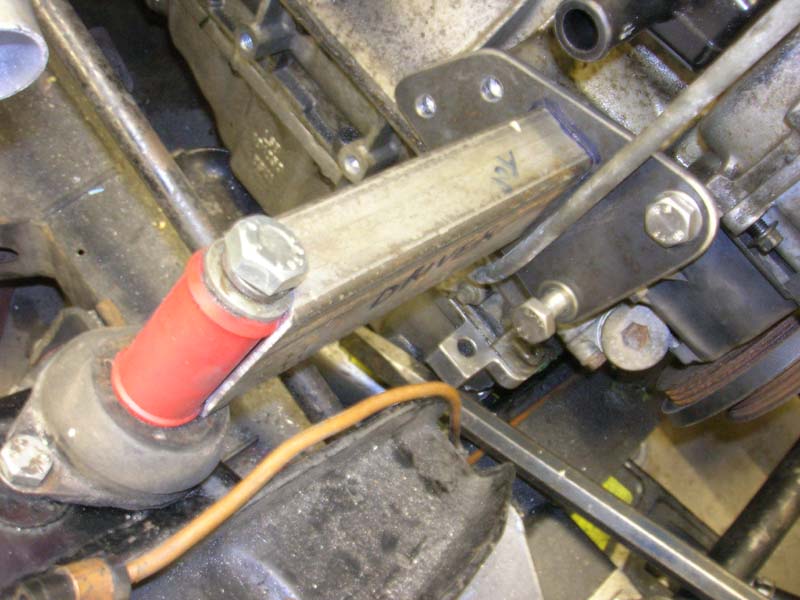
Made some bridges for my mounts.
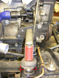 The polybush is just a dummy, its exactly the same O/D as the steel tube I will replace it with once I get down the engineering shop.....This is pretty much exactly what Caterham use.
The tube I will make for the ends where the polybush can be seen will have a just over 1/2inch hole through them for the 1/2" bolt. I will find and weld on two big flat washers on the bottom where the tubes sit on the engine mount, to spread load a bit eh?
I need to use the lathe to finish off the mounts.
The E-Type engine mounts need a small box section making up and welding on to extend the plane the mount is sat on, backwards, will also house a captive nut/bolt for the mount... this is so there is something flat for the entire thing to mount on!
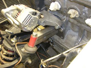
I could have made a 100 different styles of mount this just ended up as is cause its made use of what I had!
Its a bit over-engineered maybe :)
Have to heatshield the alternator its gonna get smoked by the exhaust Not sure it'll end up sitting so low...Could rehouse it on the otherside if needed...
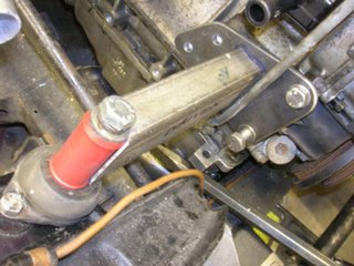
So to move on I need to buy some new mounts as they are not 100% in shape having had a 300kilo e-type engine on them! also make the flat sections they sit on, once thats done I can get them both in place and welded.
Then onto the rear gearbox mount, I'd like this to be removable rather than welded in...So will probably cut 2 recentangles of steel about 8mm thick, 4inches long by 12mm wide, cut two threads into each, at the ends ..weld them to the top of the chassis rails and run a "u" style mount that slips down between the rails and bolts in at the top...
Also cut off the straight outlet pipe from the water outlet manifold that goes on the back of the head...refaced the remaining flange ready to accept some alloy pipe sections I will make up. These will run from this outlet over the exhaust manifold, forwards to meet some flexible hose by the timing belt cover. This manifold and pipe will be one section and mount to the engine. You can buy a similar item from caterham as with the engine in RWD form the outlets are all wrong. Space is a bit lacking so custom item needed.
I can weld on a suitable alloy nut to this pipe so I can fit a temp gauge...
Once the engine is mounted at the front I can undo the 210NM front pulley nut and get the pulley on the lathe...I couldnt touch it with the engine loose on the floor! Too light even with me standing on it.
Did I mention a bare K is under 90kilos :)
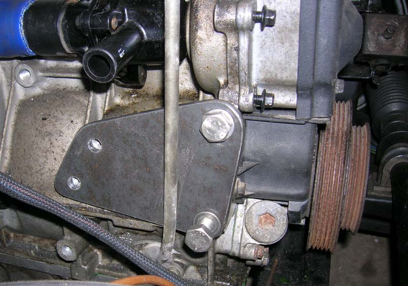
 That's basically the deal on oneside. Pump just dangles its pretty solid.
 This little bracket will be welded to the tube this obviously holds the water rail in location.
 Radiator fan sensor in background this always goes on the inlet side of the water system, I like this best, as it on the outlet it gives a false reading. On the inlet side it measures when the radiator is needing assistance.
  The black thing is stock thermostat housing I think I will modify this eventually but for now it will do for eyeing it up and testing. The open outlet is the standard bypass circuit inlet this will need blocking. I would like to knock out this whole housing and weld an alloy tube to the block but that can be done before the engine goes in finally, need the engine out for that. Its only weakness is at the redline, which is a funny rubber seal joint I don't like the look of.
 Hardly an assault on it :)